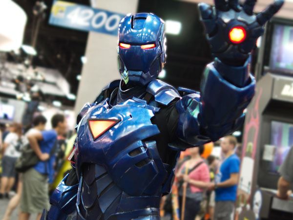
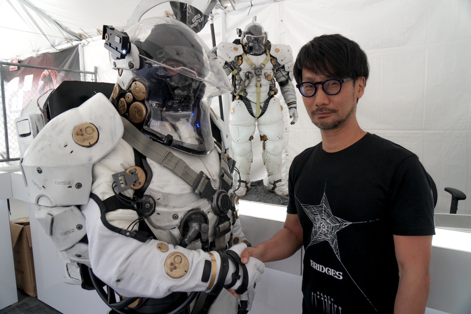
Stealth Iron Man by Andrew Makes Things
Photo by David Lee, Popular Mechanics
I originally made this post in 2012 for the 2012 Halloween Costume Contest. I surprisingly won one of the Grand Prize slots with this write up! Now that I have established my own blog, I am migrating this post onto here. After reviewing, there is still a lot of stuff I could have wrote about so if any of you have any questions, please feel free to comment and some time in the future I will be posting up more details about stages I feel need more detail.
—
This post outlines everything I did to create my first Iron Man suit with a motrized faceplate/helmet. I have always loved the look and concept of Tony Stark’s Stealth armor. This was the first serious costume I ever made and it was a lot of learning through the entire process. Start to finish took me about 8 months during my free time. I’ll caveat that all these techniques or methods are by no means my own and I have learned from many great people out there. I am simply documenting the methods I used from all the wonderful resources out there on there net.
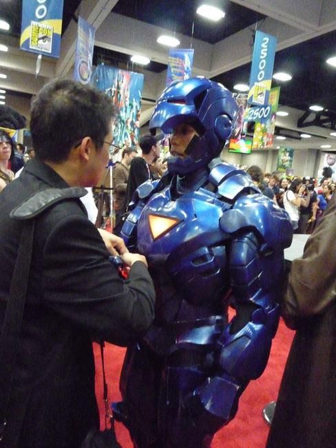
Some photos suited in in the armor:
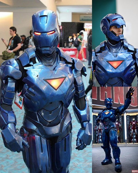
My Fiberglass/Foam Stealth Iron Man, Photos by comingsoon.net, Aaron Berkovich, and Nicole Ciaramella
And now on to how I made it!
—
Stage 1 – Form Paper Base
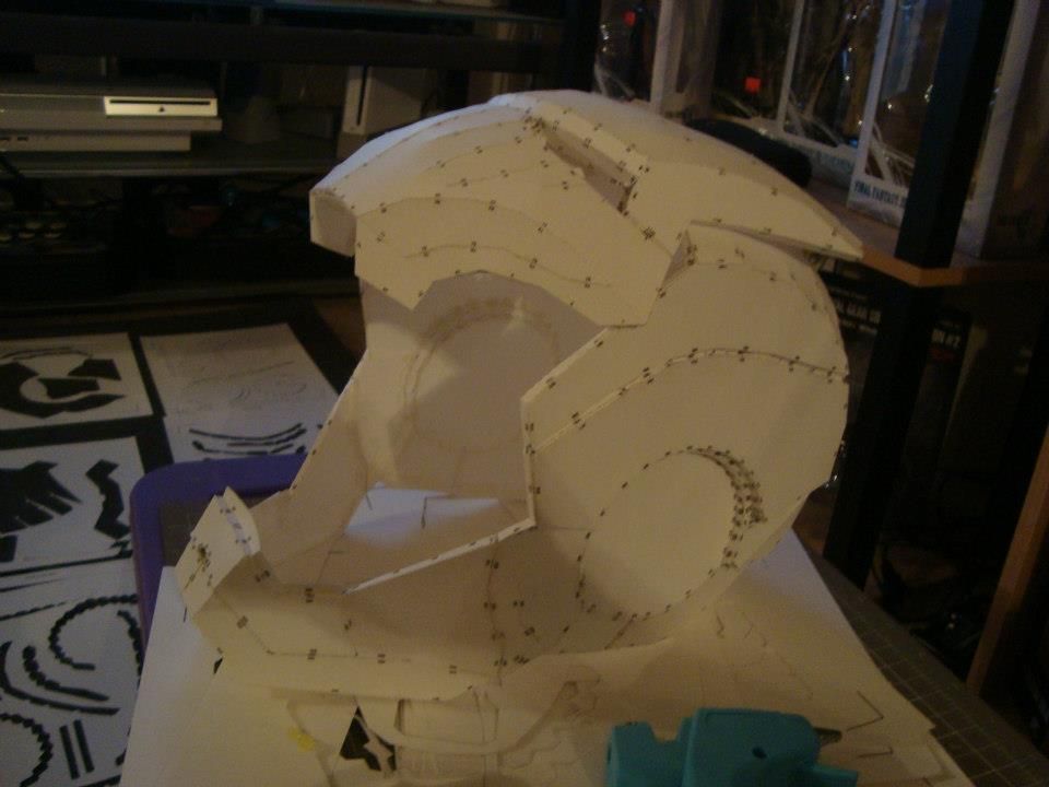
Pepakura Iron Man Helmet
Materials I used for this stage (Paid links):
- Card Stock – 110 lb

- Graphtec / Silhouette SD Craft Cutter (formerly CraftROBO)
NOTE: The Silhoette SD is no longer being made. It’s replacement is the Silhouette Cameo
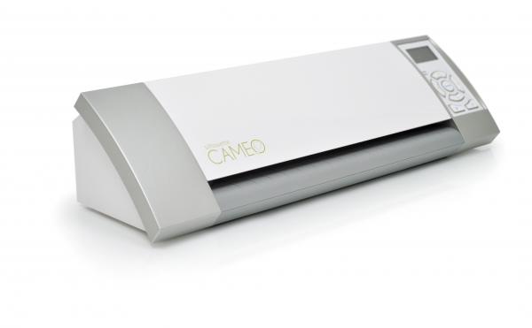
Silhouette Cameo Craft Cutter
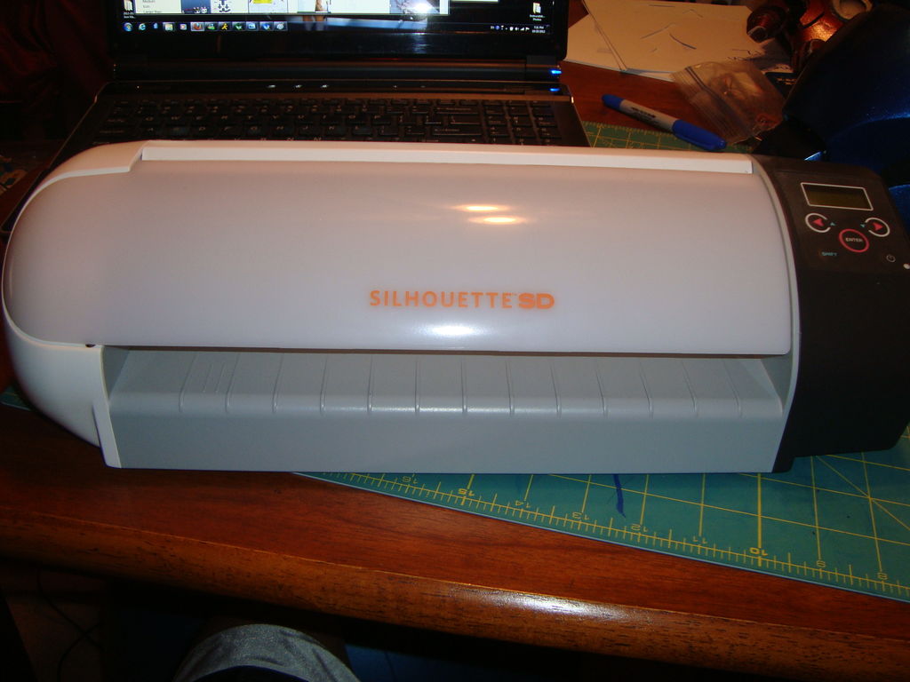
Silhouette HD Craft Cutter (CrafRobo)
- Printer that can accommodate 110lbs cardstock (This one has worked well for me:
HP Officejet Pro 8600 e-All-in-On Wireless Color Printer with Scanner, Copier & Fax) - Low Temp Glue Gun + glue sticks
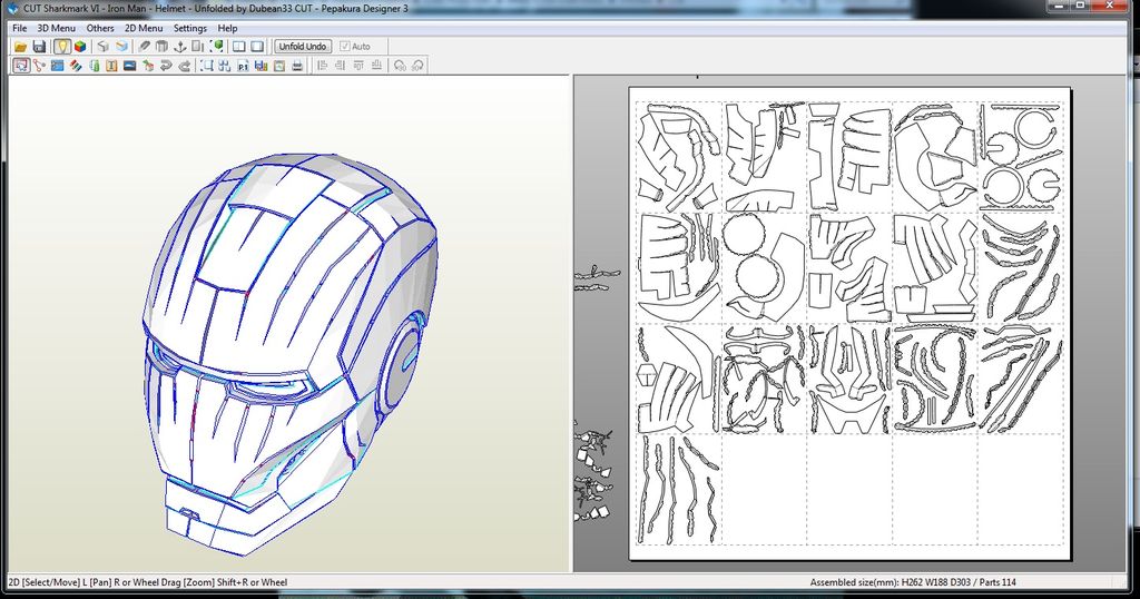
- Pepakura Designer
- Pepakura Viewer for Craftrobo

Screenshot of Pepakura Software
Steps:
- Find 3D model of the file you want to build. Google does wonders. The model I used for my Stealth Mk VI was made by robo3687. These 3D models will serve as a rough geometric base of what you are trying to build
- Download required software to open and print your paper model. Software will show you how to glue pieces together to form the base shape of your model.
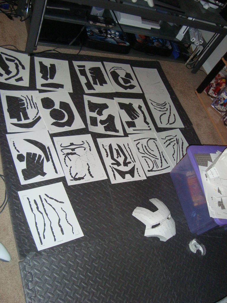
- Cut 3D model pieces with Craftrobo
- Use Pepkaura viewer to assist you in glue required tabs together

Printed Pepakura Patterns for Iron Man Helmet
—
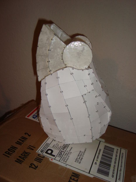
Stage 2 – Harden Paper Base
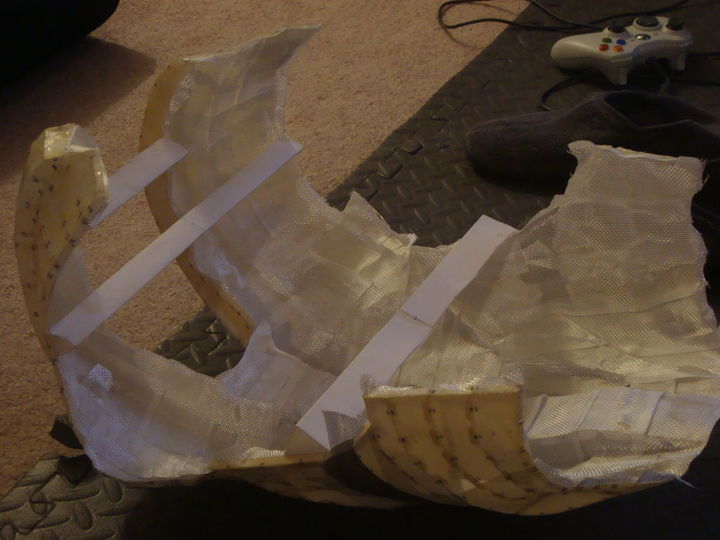
Fiberglassing the back
Materials I used for this stage:
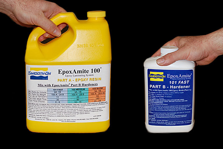
- EpoxAmite 100 Laminating Epoxy by Smooth-On

Epoxy Resin
- Fiberglass Cloth Tape (I found tape easier to use)
- Disposable Chip Brushes
- Disposable cups
- Organic Vapor Mask/Respirator <strong(Don’t go cheap on this! Safety is important!)
- Disposable gloves
- Disposable spoons for mixing
- Dremel (The Dremel 4000 worked very well for me)
- Dremel 60 grit sanding drums (You will go through a lot of these)
Steps:
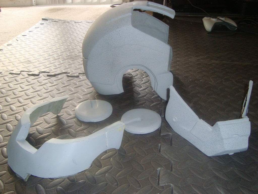
- Next, I hardened the paper base with EpoxAmite 100 (while wearing gloves and an organic vapor respirator) which is an epoxy resin that is mixed in 2 parts and applied with a chip brush. I prefer using this over polyester resin.
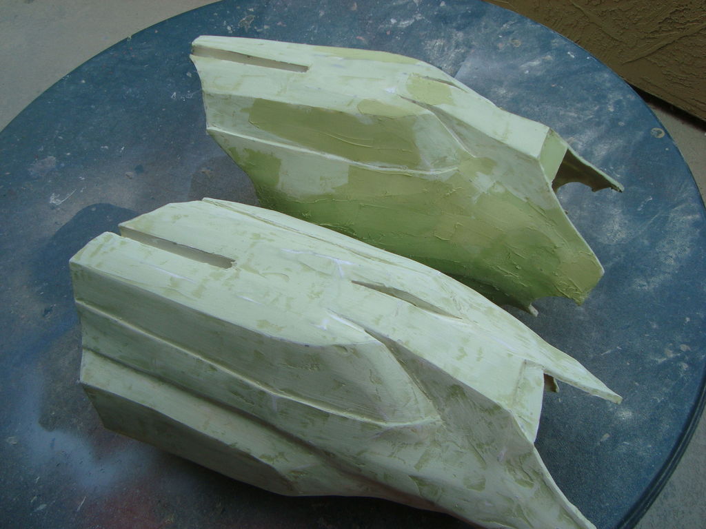
Top – Resined Piece
Bottom – No resin piece - I let the resin on paper cure over night to be safe. Once cured, the paper will be a tad bit more stiff, but will require fiberglass reinforcement in order to increase durability. Cut strips of fiberglass cloth, and use the epoxy resin to wet out the area on the inside of each piece to where you will lay the cut pieces of cloth.
- I covered the entire surface area of the inside of each piece. Overlapping the outside of the piece is okay.
- Once the fiberglass cloth cures over night, I cleaned the stray edges with a dremel with a 60 grit sanding wheel.
—
Stage 3 – Shaping with Body Filler
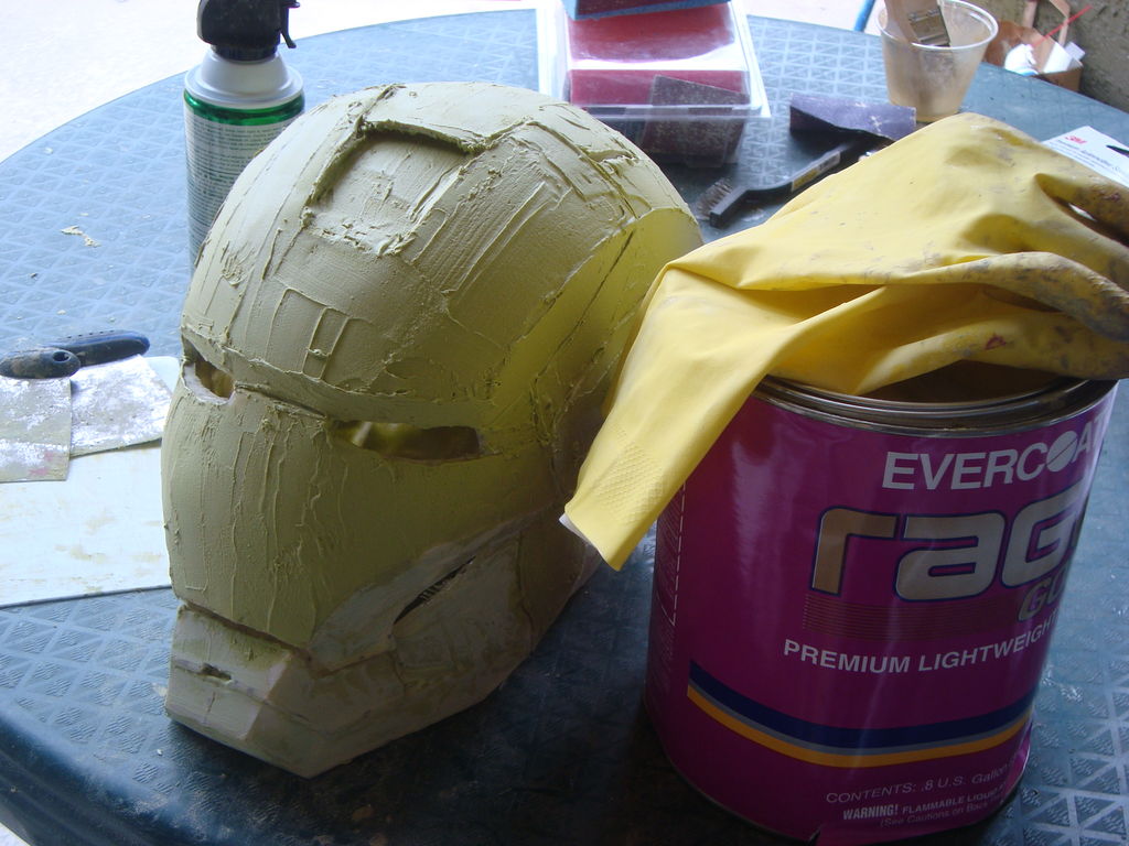
Automotive Body Filler on Fiberglassed Helmet
Materials I used for this stage:
- Automotive body filler (Evercoat 112 Rage Gold Premium Lightweight Body Filler sanded very well compared to other brands)
- U-POL Onion Board Multi Layered Mixing Palette (Made for easy clean up of body filler)
- Body Filler Spreaders (I liked the metal ones better than plastic)
- Bondo Glazing and Spot Putty
- Style Line Soft Sanders Sanding Blocks (Made it easier to sand than w/ traditional sanding blocks)
- Needle File Set
- Sand paper (60 grit, 120 grit, 220 grit, 400 grit)
- Flat (matte) black spray paint
- Automotive Filler Primer Spray Paint
-
PATIENCE
When the fiberglass stage is complete, you will have a strong piece but still geometric looking. Below is the basic process in a nutshell of how I shaped each piece and gave it more roundness.
Steps:
- Apply body filler
- Apply matte black spray paint dust coat (basically you spray your piece lightly with black paint as a guide coat when you sand… while your sanding, you’ll know where your low spots are as they will be dark)
- 60 grit sanding
- Repeat 1-3 until shape is appropriate (I took careful attention to add body filler to the low spots first which will be obvious because of the matt black dust coat)

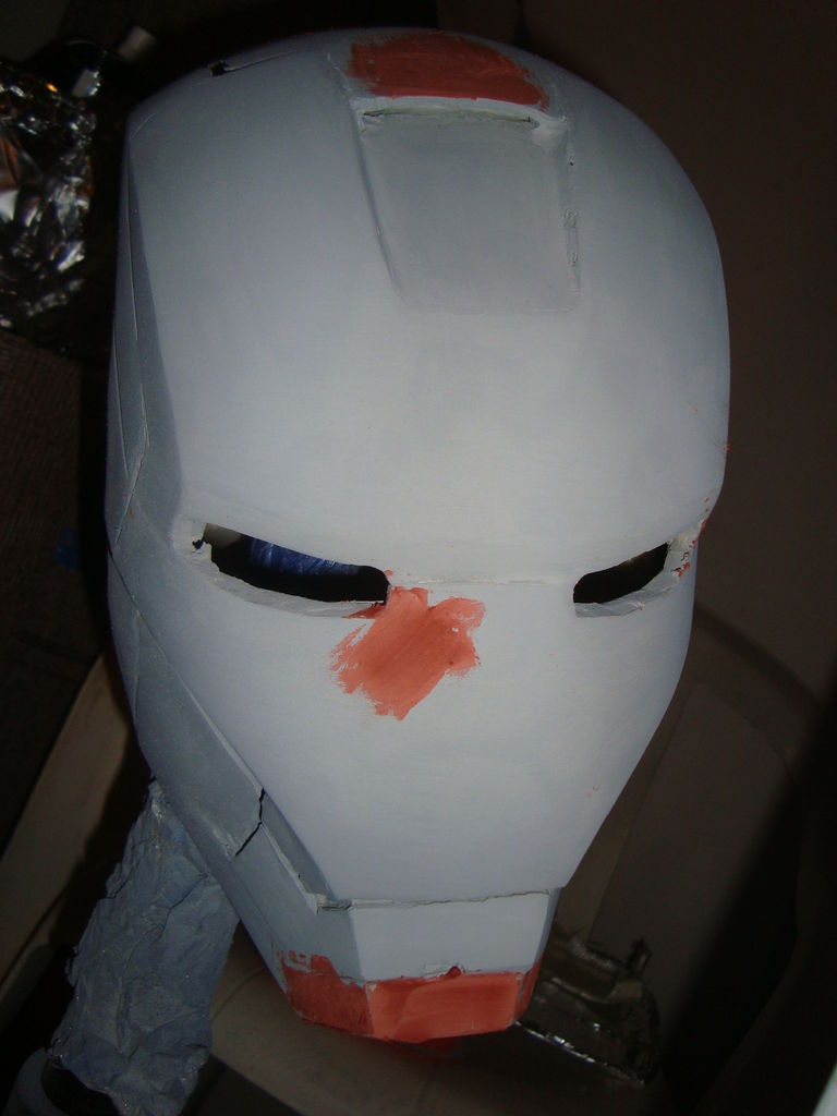
Dark spots are portions that need sanding or more filler
- Dust coat
- 180 grit sanding (this will smooth out the scratch marks from the 60 grit)
- Filler Primer (This will fill minor scratches and reveal further imperfections)
Primed Helmet – Light Black Specks are from dust coat
- Added detail lines with a needle file. These are lines that are not a part of the original 3D model that need to be etched in
- Use bondo spot putty to fill small imperfections on shape
Red spot putty on imperfections
- Dust coat
- 220 grit sanding
- Reprime to remove scratches
- Light Dust coat
- 400 wet sand
——–
Stage 4 – Painting and weathering stage
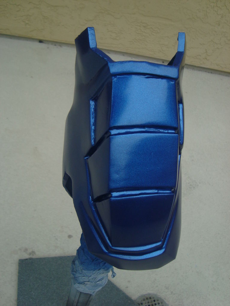
Painted bicep – No clear coat
Materials I used:
- Automotive spray paint (I used Rust-Oleum Cobalt Blue- Metallic for the “Stealth” paint scheme)
- Automotive Clear Coat Spray Cans
- Small Paint Brush Set for detailing
- Black acrylic paint
- Rub ‘n Buff Wax Metallic Finish, Pewter
Steps:
- After each piece was primed and wet sanded with 400 grit, the piece is ready to paint
- I applied 3 cost of spray paint, 10 minutes between coats
Watching the paint dry
- 30 minutes after the last coat of colored paint, I applied 3 coats of automotive clear to protect the paint and give it some extra shine
- The next day, I used a small detail brush and acrylic black paint to “dirty” up the armor. I would apply the acrylic paint, then wipe off the excess with a wet rag.
- The last part to give a damaged look is applying some Rub N Buff with a small detail brush and carefully rubbing off the excess to give a scratched metal effect
Scuff marks (Rub N Buff) and black “dirt” (acrylic paint) applied
—
Stage 5 – Flexible Pieces
Foam abs and obliques
Materials I used:
- EVA foam (Different types of Anti-Fatigue Floor Mat works well. Stick with 1/4 thickness)
- X-ACTO Knife
- Xacto Board Cutter (for angled cuts)
- Mod Podge
- Plasti Dip Rubber Coating Spray (Takes about 6 cans for an entire suit)
- Automotive Adhesion promoter (Bulldog Adhesion Promoter is pricey but an excellent brand that adds some flex)
- Automotive spray paint (Same as last step)
- Krylon Low Odor Clear Gloss Spray (This particular clear coat gave good flex)
- Chip brush
Steps:
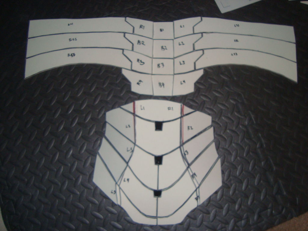
- I used form for pieces that I felt would need more flexibility. I used the foam method for the hands, abs, neck, and codpiece.
- You can google foam templates for various pieces which you will print and cut with Pepakura Viewer.
- Once I printed and cut the template, I traced onto my foam pieces.
- Using references pictures of the part I was trying to build, I varied the angle of cuts in order to get the appropriate shape for when the piece is glued together.
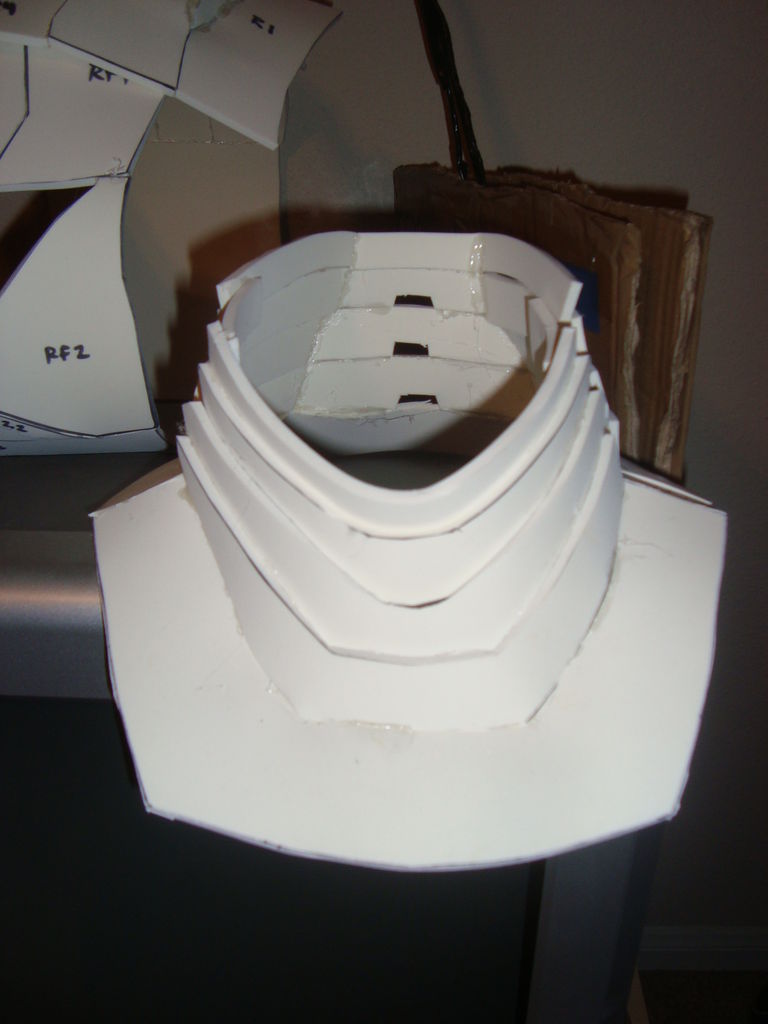
Foam Neck
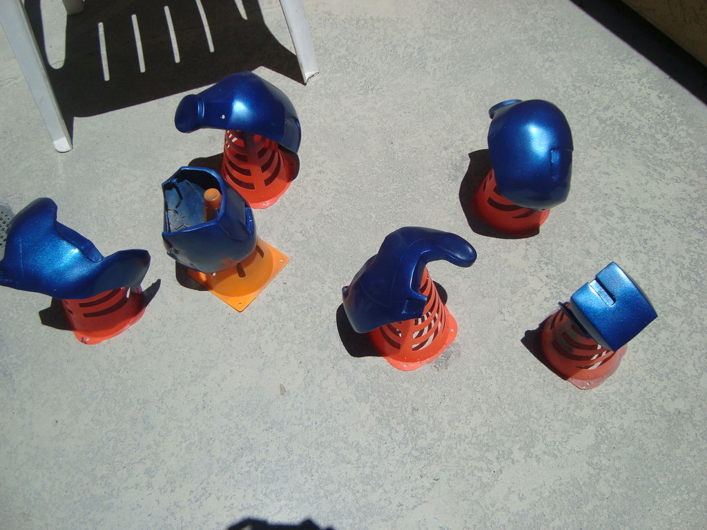
- Once the flexible pieces were build, I sealed the foam with a layer of modpodge, then 3 coats of black plastidip
- Automotive adhesion promoter was then applied in 3 coats, then the sprayed with color within10 minutes of the promoter drying
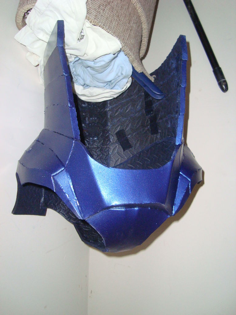
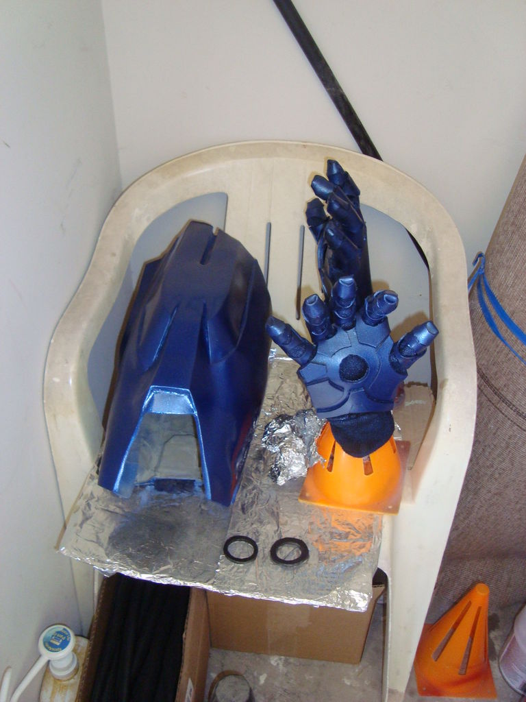
Foam Torso Painted
- After the color paint was dry, I used the Krylon gloss to give the pieces some shine
- I then weathered the pieces as previously described
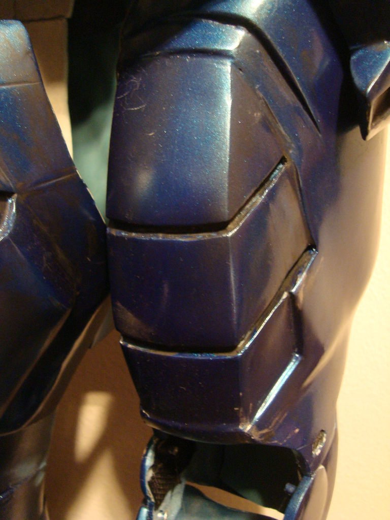
Comparison
Thigh – Fiberglass
Gauntless – Foam
—
Stage 6 – Mounting
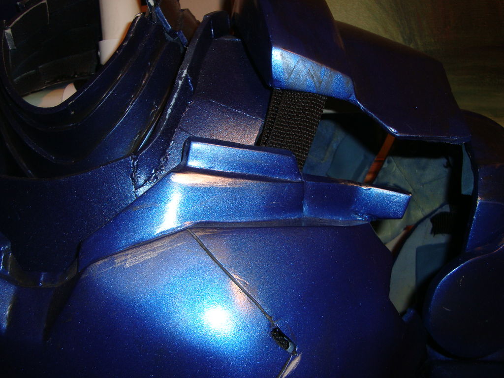
Strapping connecting chest and back
Materials I used:
- Backpack strapping
- Backpack buckles for straps
- Rare earth magnets
- Dremel
- Dremel Grinding Stone
- Industrial Strength Velcro
- Hot glue gun with hi temp glue stick
- Stretchrite 1 1/2-Inch by 10-Yard Black Heavy Stretch Knit Elastic Spool
Steps:
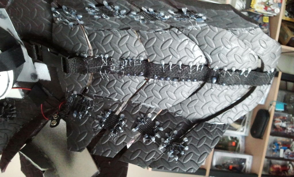
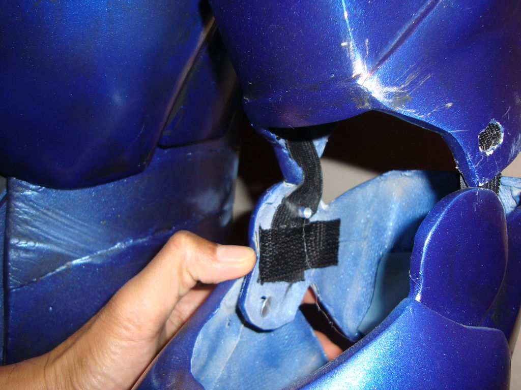
- For the flexible parts, I used a combination of Velcro and rare earth magnets

Strapping behind abs
- I used a dremel with a grinding stone attachments in order to create a space where the rare earth magnet can fit
Magnets embedded in neck
- I used hi temp hot glue in order to hold the magnet in place
- For the elbow joints, I hot glued elastic straps for more mobility
Elastic connecting bicep and forearm
- To join the shoulders to arms, I used hot glued backpack strapping to easily hook the pieces together. I did the same with the chest and back pieces.
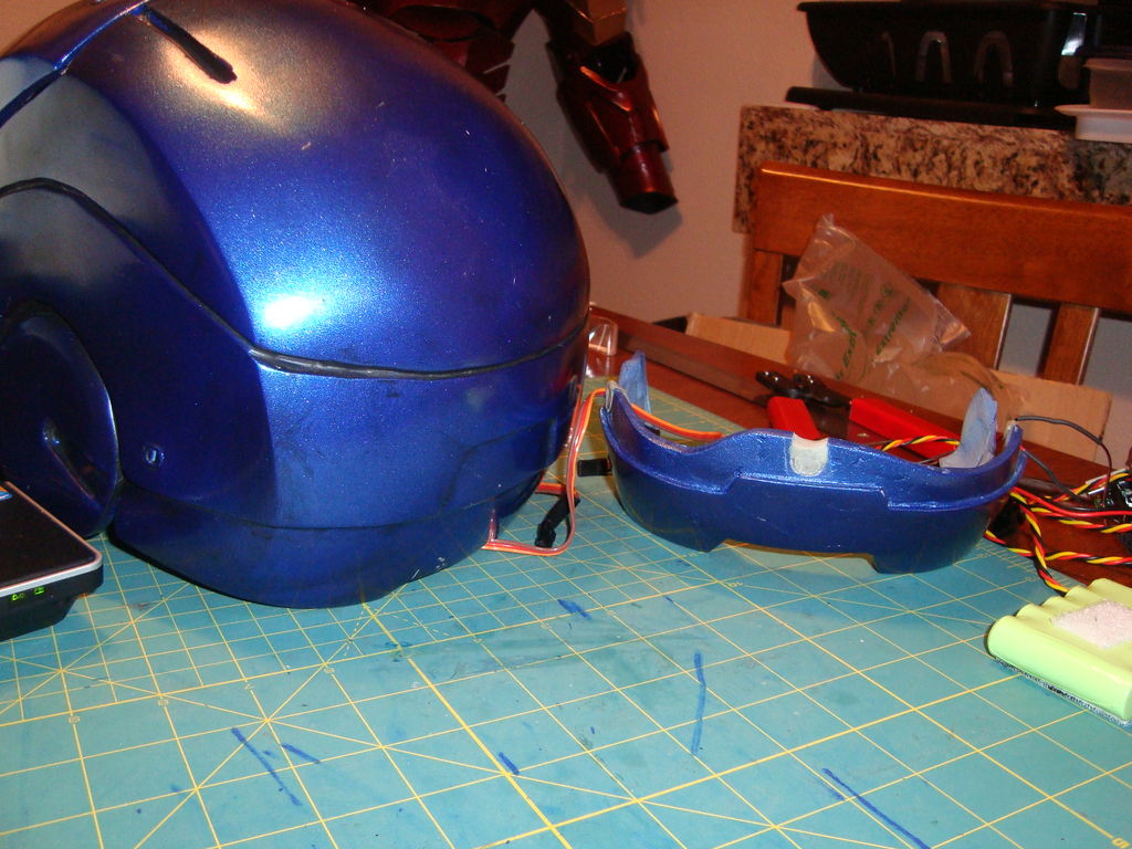
- In order for my helmet to fit, I dremeled the rear piece out and then attached magnets to the inside with Apoxie Sculpt clay.
Magnets on embedded on helmet piece
—
Stage 7 – Electronics
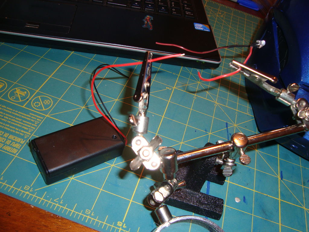
“Helping hands” holding LED and battery holder for soldering
Materials I used for this stage:
- Helping Hands with Magnifier
- Soldering Station
- Lead-Free Solder
- 22 gauge wire
- 9v batter holders
- LEDs
- Scrap foam
- Hot glue
- Velcro
- Mylar folder
- Reed switch
Steps:
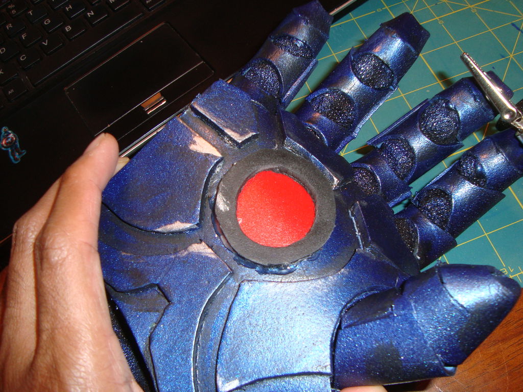
- For the gloves, I had a 9v battery holder which contained a switch. I wired and soldered this directly to my LEDs and hot glued the LEDs to the glove
- I cut out pieces of a mylar folder in order to diffuse the LED.
Red mylar folder used to diffuse light on gauntlet
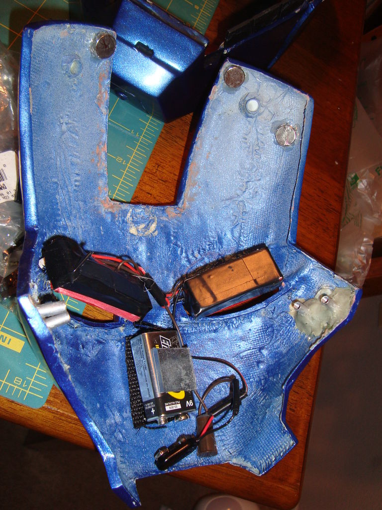
- For the eyes, I made eye boxes out of scrap foam and attached LEDs to the inside. More folder used to diffuse the light
- LED eye boxes are then wired to a reed switch and a 9v battery holder. The reed switch closes the circuit when a magnetic field is present (facemask open, eyes off – facemask closed, eyes on)
Wiring of the facemask eyes
- For the chest piece, it was more or less the same with LEDs wired and more red folders to diffuse the light.
—
Stage 8 – Servos and hinges
Materials I used for this stage:
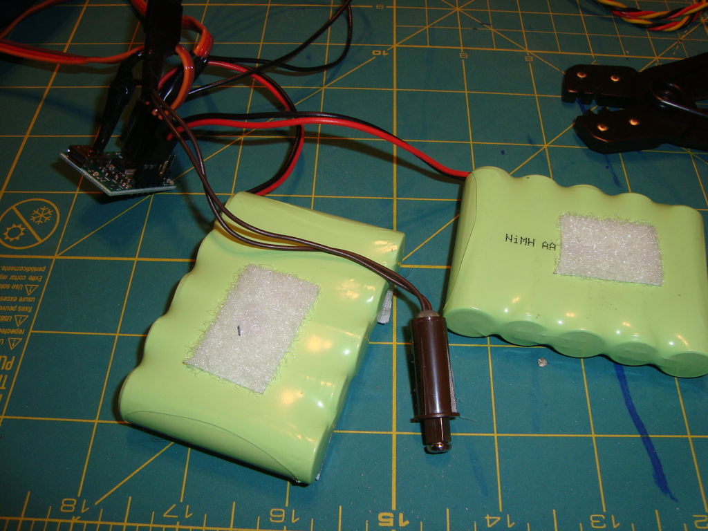
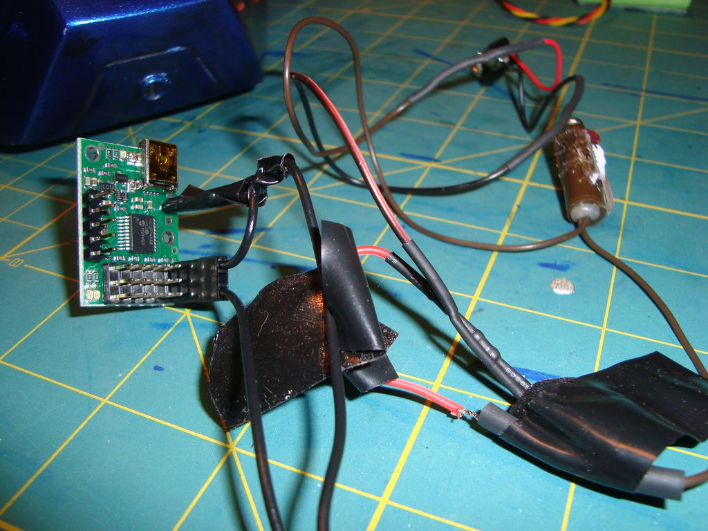
Batteries + switch + microcontroller
- Servos (I used 2 x HD-1501MG High Torque MG Servos)
- Push rods
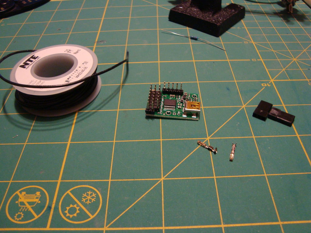
- Pololu Micro Maestro 6 microcontroller + Users guide (I now use the Mini Maestro 12-channel USB Servo Controller)
Pololu 6 Channel Microcontroller
- Wire
- 100 ohm resistor
- Soldering Iron
- USB cable
- 2 x 6v RC batteries
- Chicago Screws
- Sintra plastic sheets
- Hi temp hot glue
- Apoxie Sculpt
Steps:
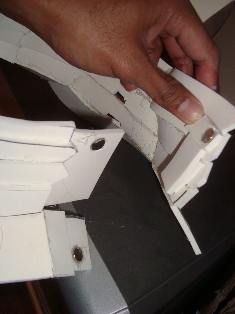
- I purchased hinge plans and installation guide from another Iron Man maker to save me the time of designing hinges, although there are a lot of other good sources on the hinge topic out there
- I made the hinges out of sintra. I cut them to shape then sanded down the rough edges.
- I glued Chicago screws into place for the hinges, and then used Apoxie Sculpt to fixate them in place. I sanded down the excess as well.
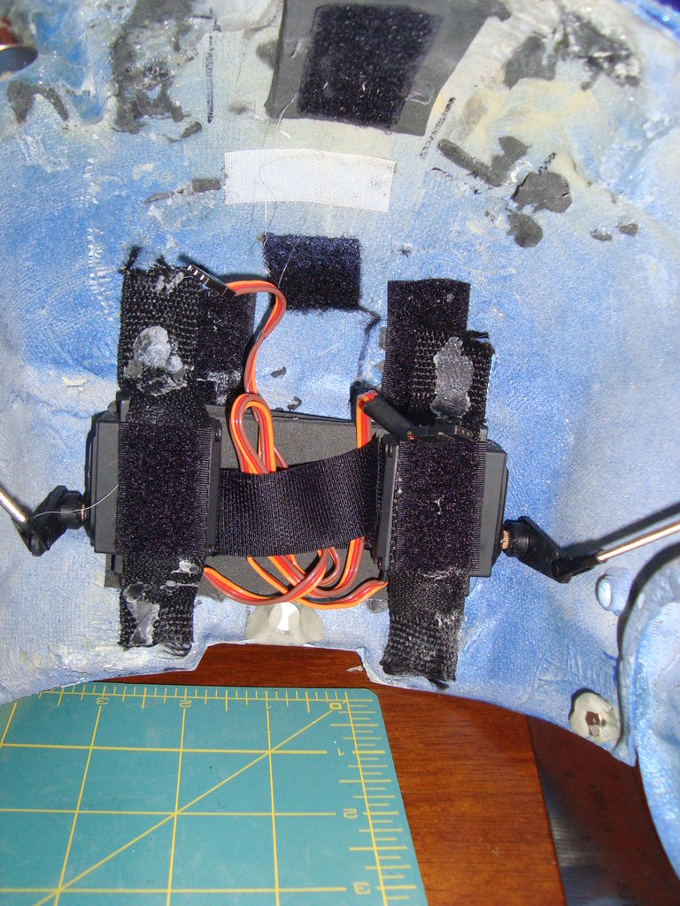
- One I had smooth movement of my faceplate, I began the installation of 2 servos in the helmet. I experimented with different positions of the servos, but ultimately the initial suggestion of having the servos in the back of the helmet became the best working. I hot glued them which seemed to hold fine.
Servos mounted in helmet
- I then measured and cut down pushrods to connect the servos to the hinges. I manually tested the motion in order to determine that the placement was satisfactory
- I then followed the manual for the Micro Maestro microcontroller in order to wire a button to one of the chip’s channels. This will be the button that activates the servos
- I followed the example script in the manual in order to have a push of the button activate servo movement. Once understanding single servo movement, I modified the script to move both servos
Micracontroller with wiring
- After having both servos in motion, I carefully modified the script in order to obtain the proper servo movement for my helmet. I noticed there was a point where the servos would rotate the hinges too far, thus warping the helmet. Once I reached that point, I returned it to a point where it would not warp.
Here’s a short video of servo action on my second helmet using the same method as the above:
—
Stage 9 – SUIT UP!
If you managed to get this far, suit up and have fun being Iron Man! Remember, patience is key for a big project like this! Questions? Feel free to comment and I will most likely make follow up posts in the future answering some of the most common inquiries.
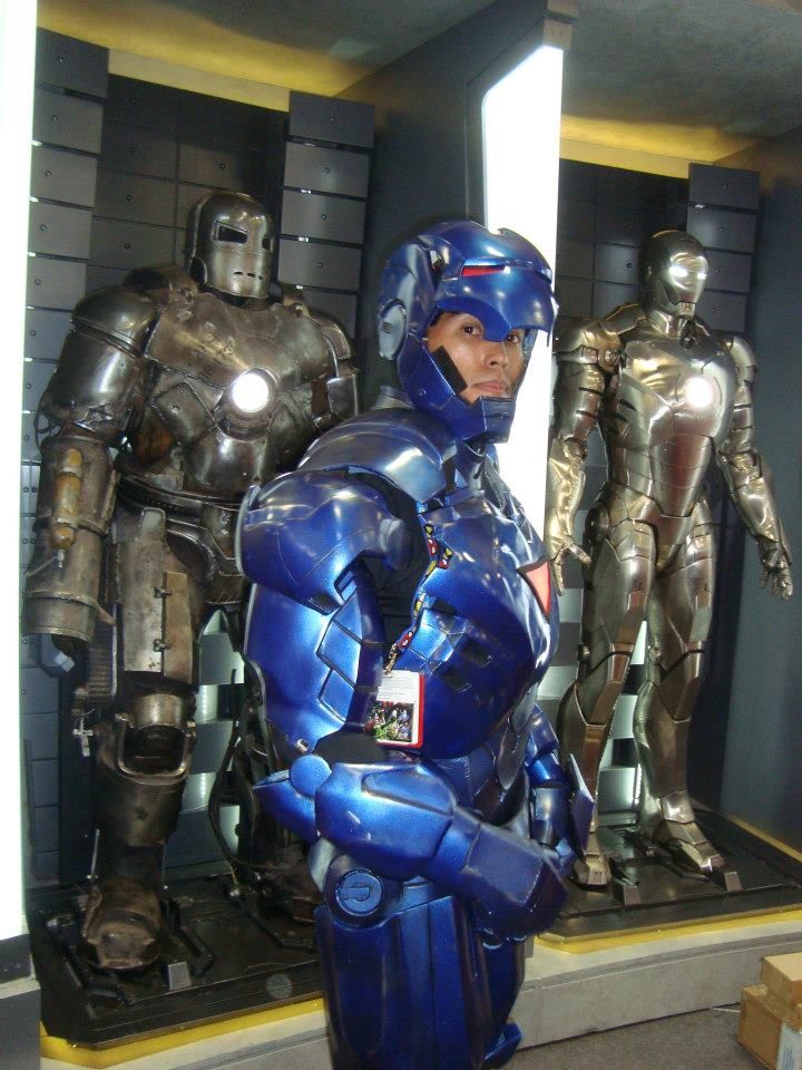
Suiting up at SDCC 2012
- Iron Man Hall of Armor


18 Comments
josh · March 28, 2014 at 2:09 pm
Do you do stuff made to order?
Andrew Makes Things · April 2, 2014 at 7:13 am
Sometimes, sure. Send me a message on my facebook page
https://www.facebook.com/andrewscosplay
Liam · April 28, 2014 at 3:58 am
Hey I have built half if my suit from helmet to abs and I was wondering what you do for peices like the forarm a where u can’t fit your hand thorough the small wrist part and also the neck
-thanks
Andrew Makes Things · April 28, 2014 at 5:55 am
I actually can fit my arm through the wrist piece. For the neck, I used magnets to open and close. I’m pretty sure there is a picture of it.
Matt · May 26, 2014 at 12:25 pm
Would you be willing to share those hinge plans? I’m interested in making this but I’d like to know if that’d be possible before I made such a huge investment. Also if you don’t mind how many LED’s did you use per hand, eye and chest piece? Thanks.
Andrew Makes Things · May 26, 2014 at 8:49 pm
They’re not mine, sorry. I had to buy them. There are a lot of tutorial vids out there though.
Deric · July 11, 2014 at 8:45 pm
out of curiosity how many coats of fiberglass did you use? did you use just on the inside? theres no pic of fiberglass stage just the resin.
Andrew Makes Things · July 13, 2014 at 2:10 pm
I used one or two depending on the piece. It also depends on the type of fiberglass you use. Certain ones are thicker/stronger than others.
Jim · August 3, 2014 at 3:12 pm
Great article here mate! Can you ballpark the total cost of materials to complete this build? Including the printers. Thanks so much!!
Emily · October 10, 2014 at 4:21 am
Hey, I was always wondering this but how do you have the faceplate open and close when you are out and about with everything on. Do you have a button somewhere or something?
Andrew Makes Things · October 12, 2014 at 9:08 pm
Re-read the section on the tutorial about the servos.
Matt · October 23, 2014 at 9:20 pm
When fiberglassing what did you cover your working surface with that won’t stick to the pieces as the resin is curing?
Matt Kradelman · November 1, 2014 at 8:14 am
What is your pricing for your cosplays? Also, what are your thoughts on making a full scale hulk buster?
Andrew Makes Things · November 3, 2014 at 3:46 pm
It really depends. You can message me on my facebook page if you’re interested in a commission.
John · November 14, 2014 at 2:07 pm
LED eyeboxes? What do you mean by that? How would you see out of them?
Working Iron Man Suit: Andrew Valenzuela | Costume Collection Blog · February 25, 2015 at 9:58 pm
[…] Q: Did you come up with the design process and ideas yourself? A: The first thing I do when I try to learn something new is to google and see what other people have done before me. I discovered there was a small costuming community that have built Iron Man costumes before so I read everything I could. The community had some awesome 3d modelers that could be used as templates to make Iron Man suits, so that’s how I got started. People who are interested can read about how I made it here. […]
iron man cosplay armor tutorial · February 10, 2017 at 5:49 pm
[…] Source: Stealth Iron Man Cosplay w/ Motorized Faceplate (Tutorial … […]
Melanie Glastrong · November 9, 2017 at 1:54 am
Such a nice blog.
I have read an amazing article here.